


For a while we have been working on a project to build a Morse code practice oscillator and accompanying capacitive Morse key, which we could use for radio practicals and to help members learn about Morse code. Now this project has been completed, we thought it was a good opportunity to write up a potted history, including the things we learnt.
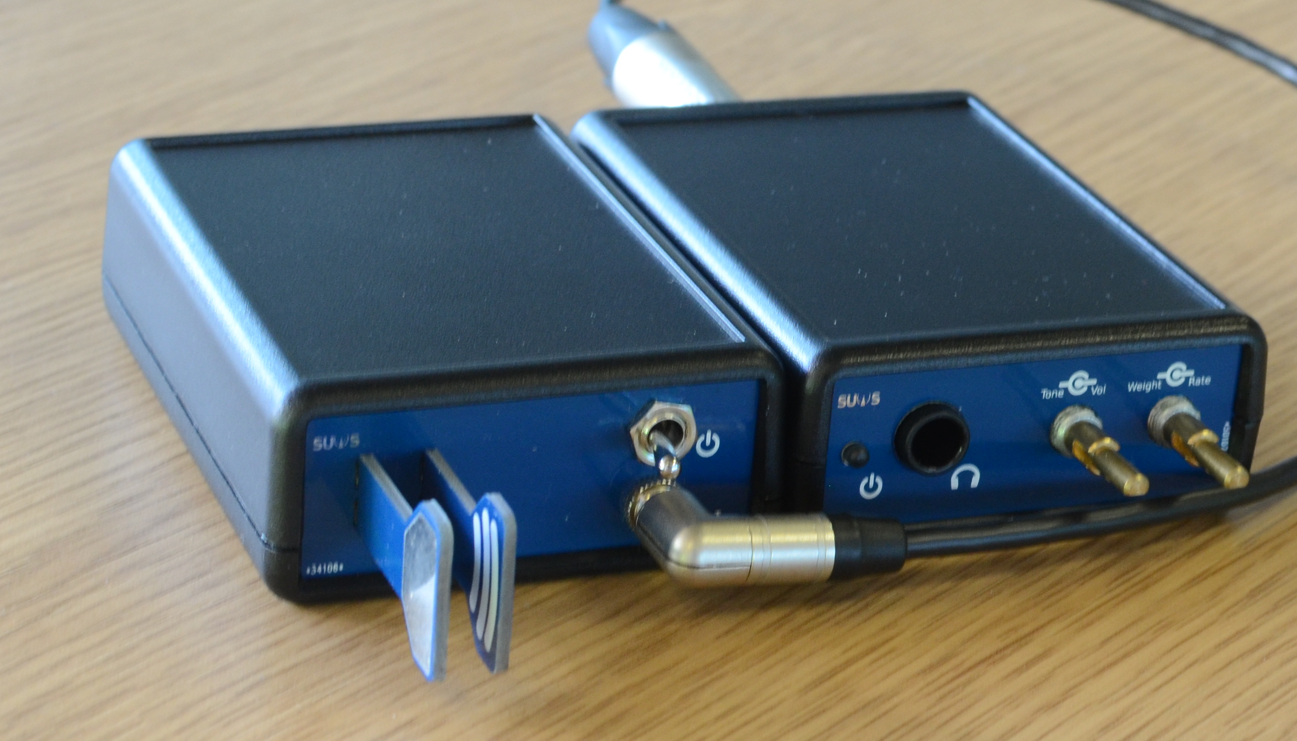
Completed Morse sounder and capacitive key
The project started with list of core requirements, in order to make the Morse key and sounder highly functional and able to meet all of our needs. The core features were that it needed to:
- take a 1/4in key jack
- have an internal speaker
- be able to be powered from batteries
In addition to this we wanted to:
- support iambic keys with variable weight and rate
- have the ability to use headphones
- be able to power it with our 12v radio power supplies
- have variable volume and tone
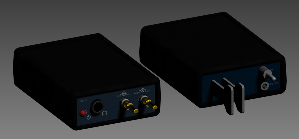
CAD renderings of the Morse sounder
The first design was made using a discrete audio stage based of some designs by Forrest Cook. We modified the designs to enable us to make the circuit using surface mount components (enabling us to fit within a compact enclosure) and to add our additional features, such as support for iambic keys. For the case, we chose the 1593 series by Hammond Manufacturing, which provided us with a compact size and would not require any post machining when used with custom end-plates. Once we had a schematic and had chosen our components, we moved onto designing the mechanics of the panels and placement of the connectors and controls using a 3D modeling tool. In order to produce professional-looking front panels, we had three options:
- Machine the provided plastic ourselves
- Laser cut the panels
- Use PCB material for the panels.
We chose the PCB option for several reasons. Unlike machining or laser cutting, the PCB option requires very little work because all the cuts and holes will already have be made prior to delivery to us. In addition, the silkscreen or exposed copper can be used to add clear labels for the connectors and controls. Producing the panels in this manner is fairly cheap, as they can fit on the same PCB as the main board. (For more information on how we did this, see the guide written by Tyler (M0UAV), one of our members). We then took the mechanical designs and schematic to produce the PCB designs and these panels.
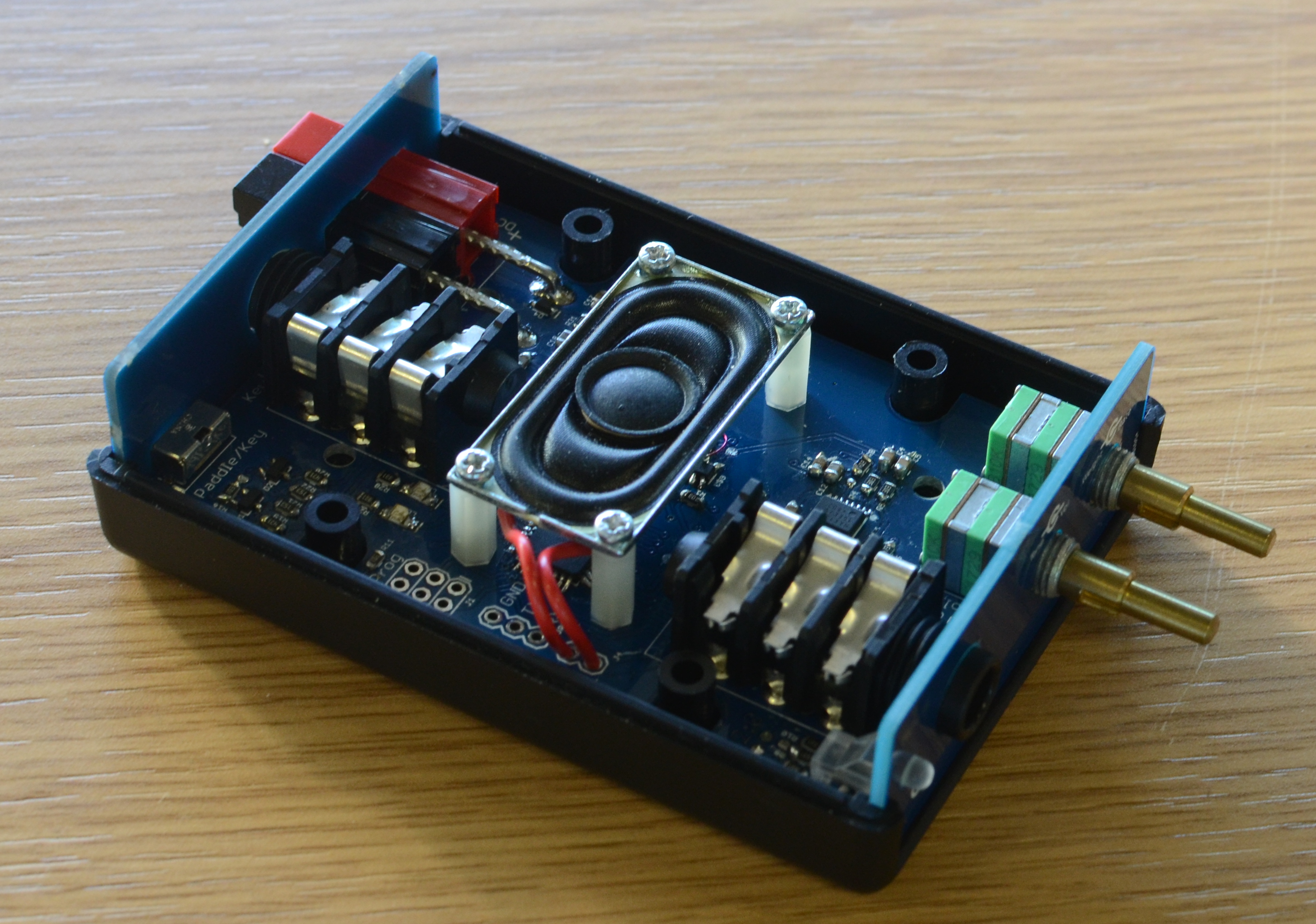
Due to the size of the front panels and main PCB, the design needed to be split across two boards to keep within the size limit for low cost PCBs. However, this still lleft some space on the second board, which we realised we could use to implement a capacitive Morse key. We based this key on some designs by M0UKD but with a new mechanical design to allow it to fit into a similar case as the sounder unit. The majority of the design for the key was done using a 3D modeling tool with the mechanical outlines from this used to design the PCBs, in a similar way to the panels.
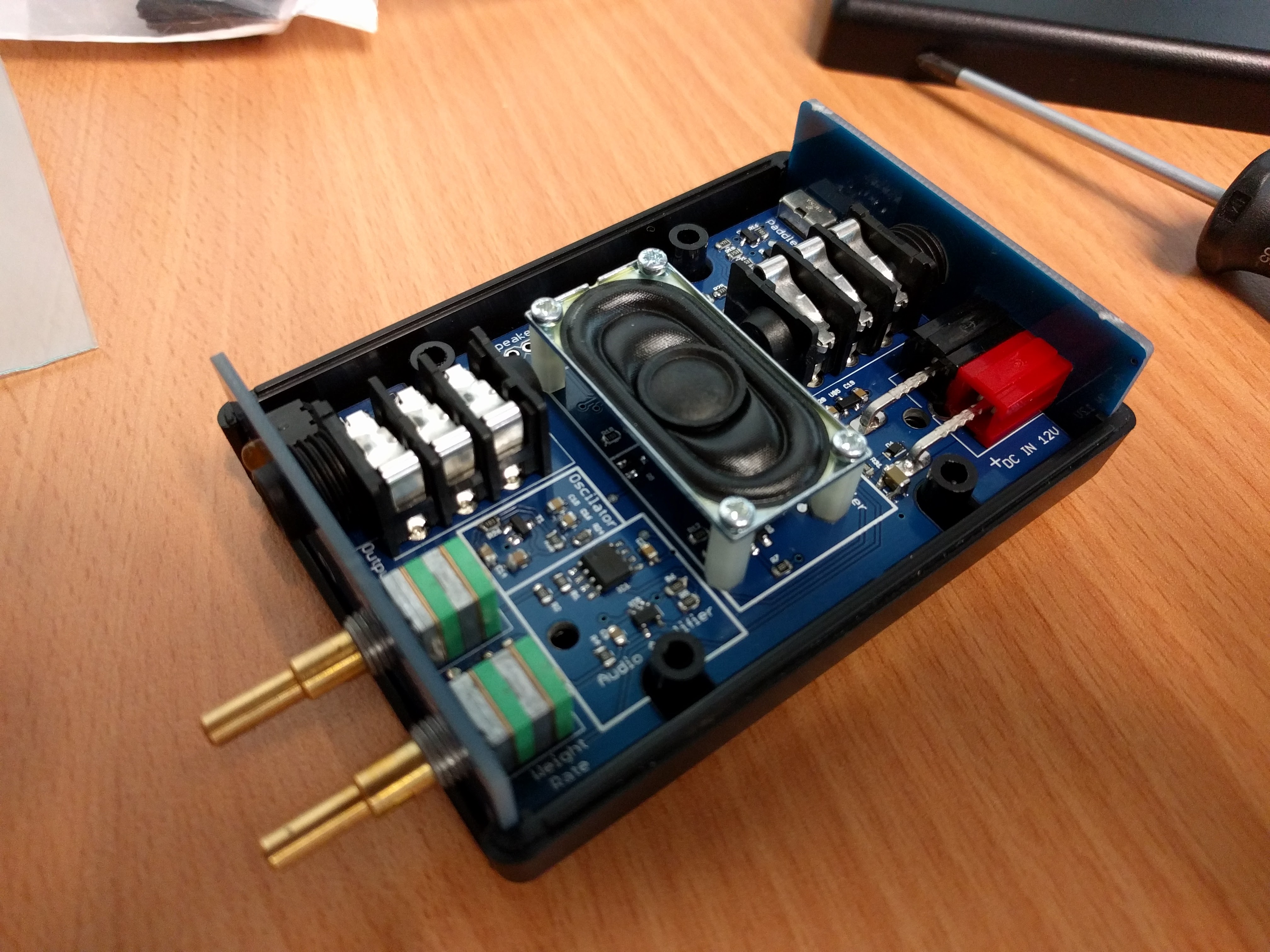
Assembled R1.0 sounder

Capacitive key internals
Once the PCBs and components arrived, we assembled a test unit to check that everything was working. While the key worked fine, unfortunately the sounder did not. There were problems throughout the audio chain, resulting in a very noisy and distorted tone output. Although several sessions were spent trying to debug these issues and work out a solution, we were unable to do so. Instead, a plan was formulated to redesign the system to be mostly software controlled with an DAC for tone generation.
The new sounder design avoids the issues faced with the previous version, as the problematic analogue circuitry has been removed or replaced with reference design implementations, including the case for the headphone amplifier. The connector locations were kept the same between the two designs, in order to allow the previous rear panels (which share a PCB with the key) to be used. We made a change to the front panel to accommodate a RGB status LED. However, as this was the panel attached to the main board, this could be remade at the same time without any additional cost.
Rev2.0 sounder unit
After the Rev2.0 boards and components arrived, a test unit was assembled. There was a pinout issue with the DAC chip. However, this was easily solved with some manual patch wires. After the board was assembled, the next task was to start the programming. The first task was to write code for all the peripherals, in order to check that everything on the board worked, which this time it did. With the peripheral drivers written, we could then combine these to form a functioning unit. The software for the sounder is done as a combination of a main while loop which handles the controls, and interrupts for running the tone generation, The use of the interrupts only for tone generation allows the unit to produce a clean output wave, as the tone generation is very dependent on consistent timings. With this code written, the unit was fully functional and ready for our members to assemble their own units.
If you are interested in making your own sounder, our designs can be found on our github project. Further information is also available on our project page.
Pingback: Making PCB end pannels for enclosures – scorpia