


Tunable Dipole: Difference between revisions
From SUWS-wiki
(Completed) |
|||
| (5 intermediate revisions by the same user not shown) | |||
| Line 1: | Line 1: | ||
{{Project | {{Project | ||
|Title=Tunable Dipole | |Title=Tunable Dipole | ||
|Status= | |Status=Completed | ||
|Project Lead=User:Stealthbird97 | |Project Lead=User:Stealthbird97 | ||
|Description= Tunable dipole for use in foundation training. | |Description= Tunable dipole for use in foundation training. | ||
|Image=Tunable_Dipole.jpg | |||
}} | }} | ||
| Line 16: | Line 17: | ||
* Drill Holes | * Drill Holes | ||
**[[File:Tunable_Dipole_Diagram.png|200px]] | |||
** 2 x 11mm holes each opposite each other, approximately 5cm from the end of one side of the 34mm PVC Tube | ** 2 x 11mm holes each opposite each other, approximately 5cm from the end of one side of the 34mm PVC Tube | ||
***[[File:Tunable_Dipole_1.jpg|600px]] | |||
** 2 x 5mm holes separated enough to wrap a number of coils of coax around the PVC tube. | ** 2 x 5mm holes separated enough to wrap a number of coils of coax around the PVC tube. | ||
***[[File:Tunable_Dipole_2.jpg|600px]] | |||
** 1 x 5mm hole in endcap. | ** 1 x 5mm hole in endcap. | ||
* Assembly | * Assembly | ||
** Screw in BNC sockets to top two holes nearest the end of the PVC tube (the Top). | ** Screw in BNC sockets to top two holes nearest the end of the PVC tube (the Top). | ||
** Thread coax through top 5mm hole. | ** Strip the outer of the coax so the core and shield can reach the two BNC connectors. | ||
** Wrap | ***[[File:Tunable_Dipole_3.jpg|600px]] | ||
** Thread coax through top 5mm hole. | |||
***[[File:Tunable_Dipole_4.jpg|600px]] | |||
** Solder shield to one BNC socket, and core to the other. | |||
***[[File:Tunable_Dipole_5.jpg|600px]] | |||
** Wrap coax around the PVC tube and thread coax through the second 5mm hole back into and out the bottom of the tube. | |||
** Thread coax through endcap. | ** Thread coax through endcap. | ||
** Attach bottom endcap to PVC tube. | ** Attach bottom endcap to PVC tube. | ||
** Solder BNC Male (or other suitable connection) to Coax. | ** Solder BNC Male (or other suitable connection) to Coax. | ||
** Install BNC Telescopic antennae | ** Install BNC Telescopic antennae | ||
***[[File:Tunable_Dipole.jpg|600px]] | |||
** Test antenna | ** Test antenna | ||
** Attach top endcap. | ** Attach top endcap. | ||
Latest revision as of 21:30, 12 April 2018
| Tunable Dipole | |
|---|---|

| |
| Status | Completed |
| Project Lead | User:Stealthbird97 |
Tunable Dipole
Tunable dipole for use in foundation training.
Parts List
- PVC Tube
- 2x BNC Socket
- 2x BNC Telescopic Antenna
- RG-58
- BNC Male Connector (or another suitable connector)
Construction Method
- Drill Holes
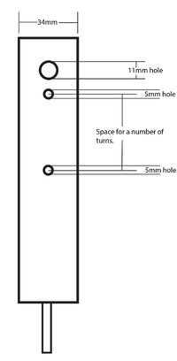
- 2 x 11mm holes each opposite each other, approximately 5cm from the end of one side of the 34mm PVC Tube
- 2 x 5mm holes separated enough to wrap a number of coils of coax around the PVC tube.
- 1 x 5mm hole in endcap.


- Assembly
- Screw in BNC sockets to top two holes nearest the end of the PVC tube (the Top).
- Strip the outer of the coax so the core and shield can reach the two BNC connectors.
- Thread coax through top 5mm hole.
- Solder shield to one BNC socket, and core to the other.
- Wrap coax around the PVC tube and thread coax through the second 5mm hole back into and out the bottom of the tube.
- Thread coax through endcap.
- Attach bottom endcap to PVC tube.
- Solder BNC Male (or other suitable connection) to Coax.
- Install BNC Telescopic antennae
- Test antenna
- Attach top endcap.


